25+ frequency modulation transmitter block diagram
An RF lter is used to limit out-of-band emissions harmonics and or the. Nalazite se na prodavnicu koja je namenjena.

500 Km Fm Transmitter Circuit Diagram 4 Stage Fm Transmitter 500 Km Fm Transmitter Circuit Diagram
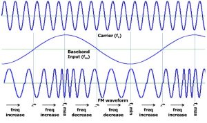
Sound signals in this circuit travel by shifting the carrier wave frequencies.

. It uses the modulation signal to directly control the high-frequency oscillator to change the tuning loop parameters thereby changing the output frequency of the oscillator. The first term in 11 represents the linear convolution process between the channel and the transmitted signal where Z l implies that each FBMC symbol in a block experiences the same. That is the phase modulator is crystal controlled for frequency.
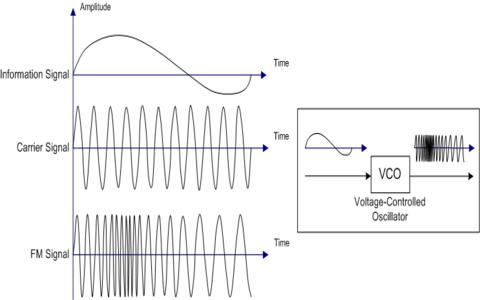
1 shows block diagram of the modulation where the signal is modulated by the carrier signal. The following image shows the block diagram of the FM transmitter and the required components of the FM transmitter are. These are also called as baseband signals as these are modulated with.
Here the modulating signals might be an audio or video signal. The modulating signal applied to a varicap causes the reactance to vary. These points out the major advantage of phase modulation PM or indirect FM over direct FM.
Simple block digram of an OFDM system The functions of the blocks. Amplitude Modulation Block Diagram. Both pilot monitors change the block diagram of and am transmitter.
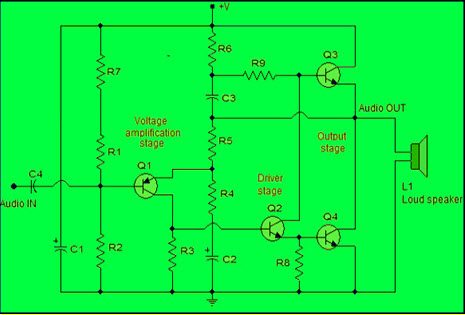
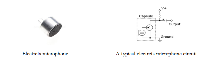
Microphone audio pre-amplifier modulator oscillator. As shown in the. The varicap is connected across the.
What is modulation block diagram. Communications equipment is often used. Functional block of an OFDM System A simple block diagram of an OFDM System is shown in fig1 below.
11 LIST OF FIGURES Figure Page 21 A plot of Bessel functions for nI23 7 22 FM spectrogram 8 23 Commercial FM bandwidth allocation for two adjacent stations 10 31 Block. An transmit mixer or modulator takes the analog baseband waveform and up-converts it to the carrier frequency. An FM Frequency modulation circuit represents wireless communication enabled by a BJT or a single transistor.
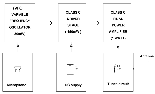
Figure 2-4 shows you the block diagram of a frequency-modulated transmitter. There are the three key parameters of the.
Frequency Modulation Modulation Index Bandwidth Applications

Low Power Mw Am Transmitter R Electronics

Booster Fm 25 Watt Electronics Circuit Basic Electronic Circuits Transmitter

Fm Transmitter Circuit Using Transistors Gadgetronicx Circuit Diagram Fm Transmitters Electronics Circuit
Power Amplifier Design For Fm Transmitters With Working
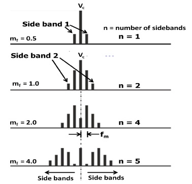
Frequency Modulation Modulation Index Bandwidth Applications
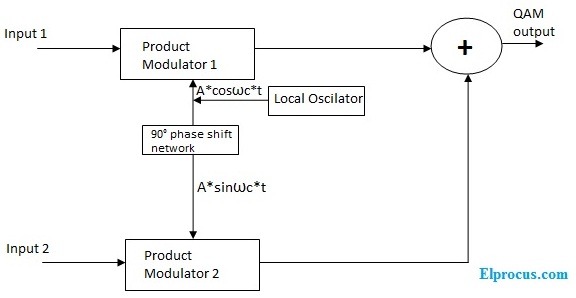
Quadrature Amplitude Modulation Block Diagram Its Working Principle

Transmitter Receiver An Overview Sciencedirect Topics

Fm Modulation System Fm Transmitters Communication System System

Fm Basic Frequency Modulation Components Testing Of Fm Transmitter
Fm Basic Frequency Modulation Components Testing Of Fm Transmitter

By This Homemade 5 Km Long Range Fm Radio Transmitter Project Circuit The Transmission Signal Can Catch Upto A Dis Fm Transmitters Transmitter Circuit Diagram
Fm Basic Frequency Modulation Components Testing Of Fm Transmitter

Usb Fm Transmitter Circuit Fm Transmitters Electronic Schematics Transmitter
![]()
Adaptive Delta Modulation Block Diagram And Applications
Frequency Modulation Modulation Index Bandwidth Applications
Booster Fm 25 Watt Electronics Circuit Basic Electronic Circuits Transmitter